Free Cooling, simply put, is using colder ambient air (colder than the supply chilled water set point) to perform cooling rather than the refrigeration cycle of the chiller. In our HVAC-systems world, the proper technical name is waterside economizer. Many people are familiar with how an airside economizer works but we are talking about a waterside economizer.
An airside economizer is typically used on a packaged rooftop or tied to an indoor AHU, allowing filtered outside air into the space when outdoor temperatures drop below 55°F (12 °C) (the common supply air temperature of indoor spaces) thus alleviating the need for the refrigeration cycle to be running. Interior space is being cooled yet the refrigeration system is not running, hence the name Free Cooling.
If we now transition back to the chiller world, the equivalent would be a free way to supply whatever temperature chilled water we need without running the chiller. Free Cooling isn’t literally free because it does require an initial capital investment to own. But payback periods can be very rapid depending on your range of ambient temperatures where you live, and the needed leaving (or supply) temperatures of your chilled water demands. For instance, it might take five years for a hospital in New Orleans to recoup their investment if running 40°F (4 °C) chilled water for an operating room suite, but it might take less than a year for a data center in Boston running 70°F (21 °C) chilled water to its servers.

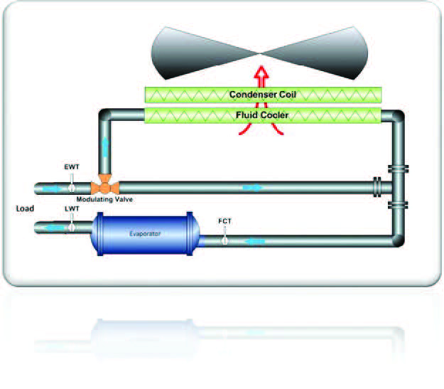
Figure 1
Types of Free Cooling
There are many ways to achieve free cooling with different types of systems. For water-cooled systems it is common to use a large plate & frame heat exchanger to transfer cooling between the cooling tower loop (when temperatures are favorably low) and the chilled water loop. There is also a thermosyphon system using colder than normal condenser water temperatures to move refrigerant around without the use of the compressor while still achieving some heat exchange at various levels, depending on the exact temperature difference. For the purposes of this article, let us focus on a more recent and expanding technology for free cooling associated with air-cooled chillers. To be clear, dedicated air-cooled free coolers, or fluid coolers, have been around for many years but now we can economically integrate this function within a packaged air-cooled chiller or a modular air-cooled chiller system.

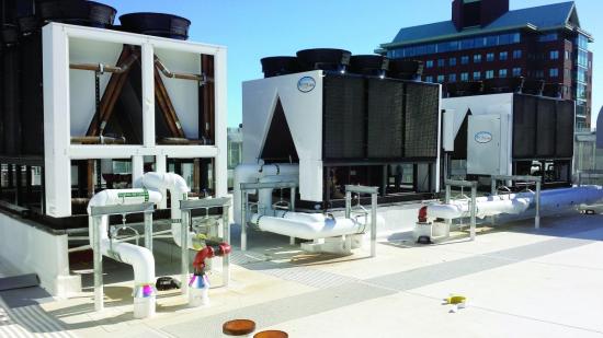
Figure 2
Operation Of Free Cooling
The operation of these systems has proven to be highly reliable and surprisingly simple. The engagement of the free cooling system is through a modulating three-way valve connected to the building load or load side of the chilled water system, the chiller system, and the free cooling system made up of a copper tube/aluminum fin water coil with condenser fans.
In an integrated system, there is a water coil sandwiched directly against the normal copper tube/aluminum fin refrigerant coil being used as the condensing surface of the air-cooled chiller with condenser fans pulling air simultaneously across both (see Figure 1). Note the three-way valve is fully configurable to an owner’s desired activation temperature (Figure 2 is a field installed chiller in Boston with access panels removed to show both coil header pipes from the side).
I. High Ambient – Under high ambient conditions, there is no potential for free cooling and therefore the free cooling coils or modules are bypassed, and 100% mechanical cooling will be used.
II. Mid-Range or Pre- Cooling – Depending on how aggressive you want to control your system; the three-way valve can begin to open to the free cooling coils between 2°F (-16 °C) and 4°F (-15 °C) below your chilled water set point. This temperature approach (difference between set point temperature and free-cooling activation) is much lower than most people realize until they study air-cooled designs. So, if a system is running at a standard chilled water temperature (44°F or 6 °C) it will start to take advantage of free cooling when the outside ambient dry bulb temperature reaches 42°F (5 °C). At these temperatures you will still need the mechanical cooling system for full capacity, but the load is now being shared and system is gaining everything it can from the ambient environment. The refrigeration system is then finishing off whatever is left with perhaps 50% of your compressors/capacity. Energy use is cut in half in this example.
III. Winter Operation – Once the system reaches the range between 5°F (-15 °C) and 9°F (-12 °C) below its chilled water set point, it can achieve 100% of its capacity with the free-cooling coils. At this point, the three-way valve will be 100% open to the free-cooling coils and the mechanical refrigeration system will be shut down. You can’t get more efficient than off. Of course, the condenser fans will continue to draw ambient air over the free cooling coils, but it will also slow down and shut off if ambient temperatures continue to fall, further increasing energy savings.
IV. Limitations – The final stage of operation is reached when cooling demand is exceeded and the three-way valve will then begin to throttle back to avoid overcooling and maintain set point. In northern climates, there will be a glycol solution in use and therefore the risk of freezing the free cooling coils is reduced. However, in southern climates where water would be used, a new limitation around the freezing point is introduced. In this case, operation below 34°F (1 °C) would be prohibited.

Different Approaches Toward Free Cooling
At the Arctic Chiller Group, we do free cooling in one of two ways: the integrated coil-on-coil in a large packaged chiller described above and also in a modular way. We are known as a modular chiller specialist so it’s no surprise we would have a modular take on free cooling that has been very popular. In this design, we start with an air-cooled bank of chillers and then add on free-cooling modules to a predetermined amount of free cooling requested.
This is a great way to maximize the amount of free cooling available but does require additional real estate to accomplish. It can be thought of as adding mini-fluid coolers with the same cabinet size as the modular chillers. It also maximizes the redundancy of the system and gives an owner the flexibility to add chillers and free cooling modules in the future as more capacity is needed. This has been a very popular approach for data centers starting with a base load and know they will need room to grow as they sell more and more co-location space to clients.

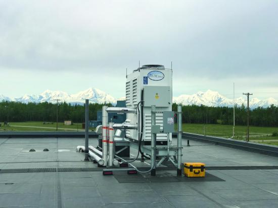
Figure 3
In Figure 3, we are showing the ArctiChill Wing Design™ which features a central pumping section where supply and return piping would connect to the bank. The pumps and the header piping system are sized for the largest future capacity that can be foreseen. We have the immediately needed free cooling modules to the right and chillers to the left. Imagine the supply water entering the bank and going right, through the free-cooling module header pipe system, and then left through the modular chiller system before returning to the building at set point. Figure 3 shows four of each but imagine if eight would eventually be needed. Structural supports and a base frame would be installed for the future modules at the beginning.
Now, an owner can easily add a chiller and/or a free cooling module only when they are warranted by a growing customer demand (and not have to spend that money beforehand). In situations where real estate is hard to find, we can also build integrated coil-on-coil free cooling systems right into modular chillers as well to minimize the footprint where needed. Where variable primary flow is advantageous, we can also build into the pumping section the variable speed drive and controls for a truly integrated system and also be open protocol to be further integrated into the whole building automation system for full transparency and control.
Source: coolingbestpractices.com