The Big Picture
Heat recovery opportunities have resulted in the largest amount of savings of our common projects our industrial energy management teams have implemented. It is not the easiest type of project to implement but the amount of savings and the reduction of emissions makes this project very worthwhile.
The first question I ask in workshops is: What is the purpose of the cooling tower located outside of your plant? The answer: To remove waste heat. Second question: Does it make sense to use a system to remove heat from your plant and then use expensive natural gas to provide heat for makeup air?
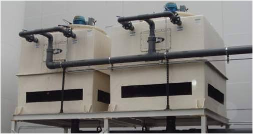
Figure 1 Cooling Tower
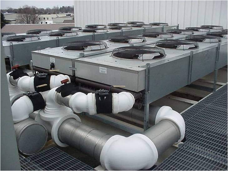
Insert Figure 2 Dry Cooler
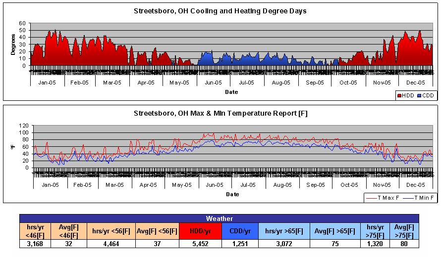
Many times I usually get the response: The low grade heat from the coolant loop is not sufficient to provide the heat we need for our factory. My answer: Is the coolant loop temperature >10 degrees F warmer than the outside winter air temperature? Then warming the incoming air will reduce the heating load. Look at this table of weather data from Ohio. There are 4,000 hours where the average temperature is less than 37 degrees F!
Figure 3 Weather Chart
Project Review
Let’s begin the review of this project. Symptoms which can help identify the opportunities for this project include:
- The facility has sources of waste heat such as cooling towers or furnace or equipment exhaust.
- The facility has a large amount of air exchange such as exhaust hoods, filtration systems, ceiling or wall exhaust fans.
- Winter heating is required such as natural gas forced air, steam, or hot water systems.
Heat Source #1: Air-cooled Air Compressors
One of the simplest projects to get waste heat is from an air cooled compressor. This is a common project but I continue to find plants where this source of free heat is not being utilized.
Figure 4 Air Cooled Compressor Heat Recovery
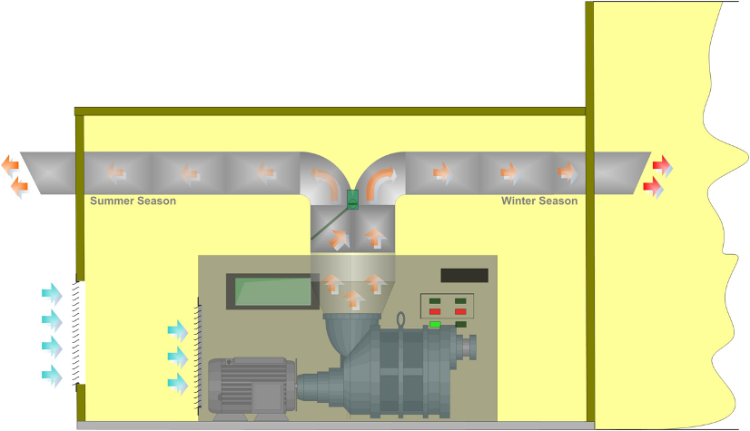
A key to the success of this project is to be sure to use outside makeup air for the intake and discharge the warmed air into the ceiling area of the facility, not directly blowing on an individual.
To calculate the value of this free heat use this simple formula:

Heat Source #2: Coolant Loop of an Injection Molder
Another method to recover waste heat is from the coolant loop. By intercepting the water at its warmest point before it arrives to the cooling tower and passing it through a radiator the heat in the water can be used to provide warmed make up air.
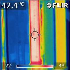
This photo shows the coolant water from an injection molding machine. The thermal image shows the temperature of the water. As you can see the temperature of the coolant water is significantly above the outside air temperature in the winter.
Figure 5 Injection Molding Coolant
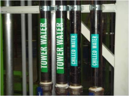
Figure 6 Injection Molding Coolant Thermal Image
Heat Source #3: Various Heat Wasters
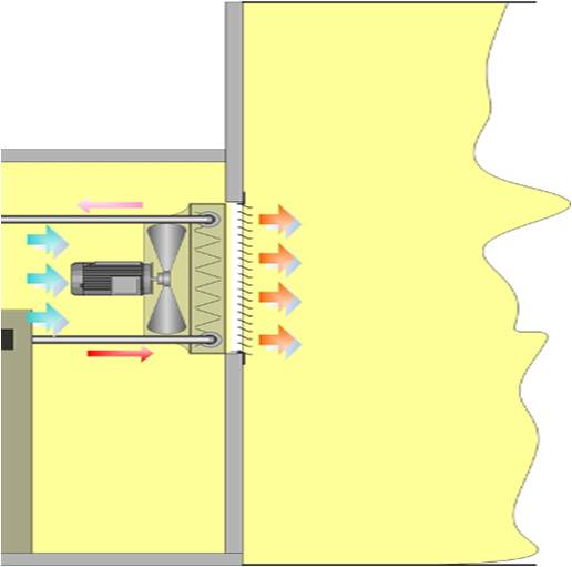
The next diagram and shows a typical installation drawing. As with the air cooled compressor it is important that this system be set up to bring in outside makeup air and then exhaust the air into the ceiling area of the facility.
Figure 7 Water to Air Heat Exchanger diagram
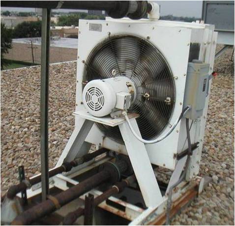
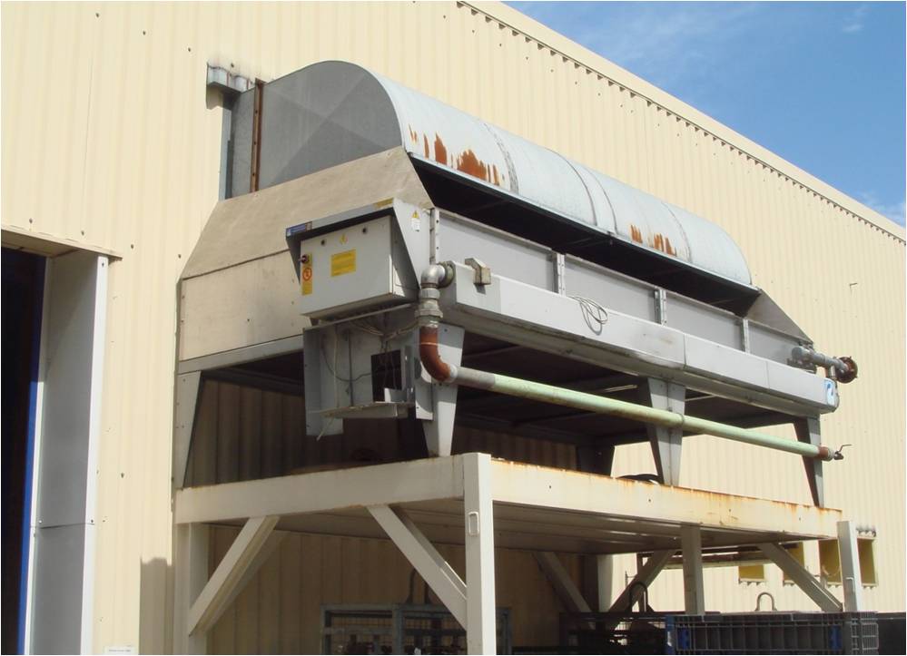
Here is a photo of what I call a “Heat Waster”. This is exactly the type of unit that could have the discharge air ducted into the plant during the winter for free heat.
Figure 8 Water to Air Heat Exchanger
Here is the formula that can help to determine the value of heat available.

Many plants have been able to reduce their winter heat loads using this concept. Many, even in Michigan and Wisconsin have been able to eliminate the need for natural gas heat during production hours.
I have found a company that supplies this type of heat recovery device along with some electronic measurement equipment which provides details of the amount of energy and savings that is being recovered from the coolant water. (www.amsenergy.com) This 100 gpm radiator unit with a metering system can cost around $25 to $30,000.
Heat Source #4: Free Cooling
Another area to find savings is called “free cooling”. The concept of “free cooling” is that when the outside temperature is more than 10 degrees below the required coolant temperature the electric chiller can be bypassed and the cooling tower can be used to provide the cooling with a much lower energy use. Many facilities, especially those with injection molding processes use electric chillers to cool molds and hydraulics. A common temperature for the cooling loop ranges from 55 to 75 degrees. Refer to the chart above and you can see there were more than 3,000 hours with an average temperature of 32 degrees in the Ohio.
This one line diagram shows how this type of system is configured.
Figure 9 Free Cooling diagram
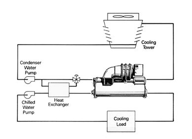
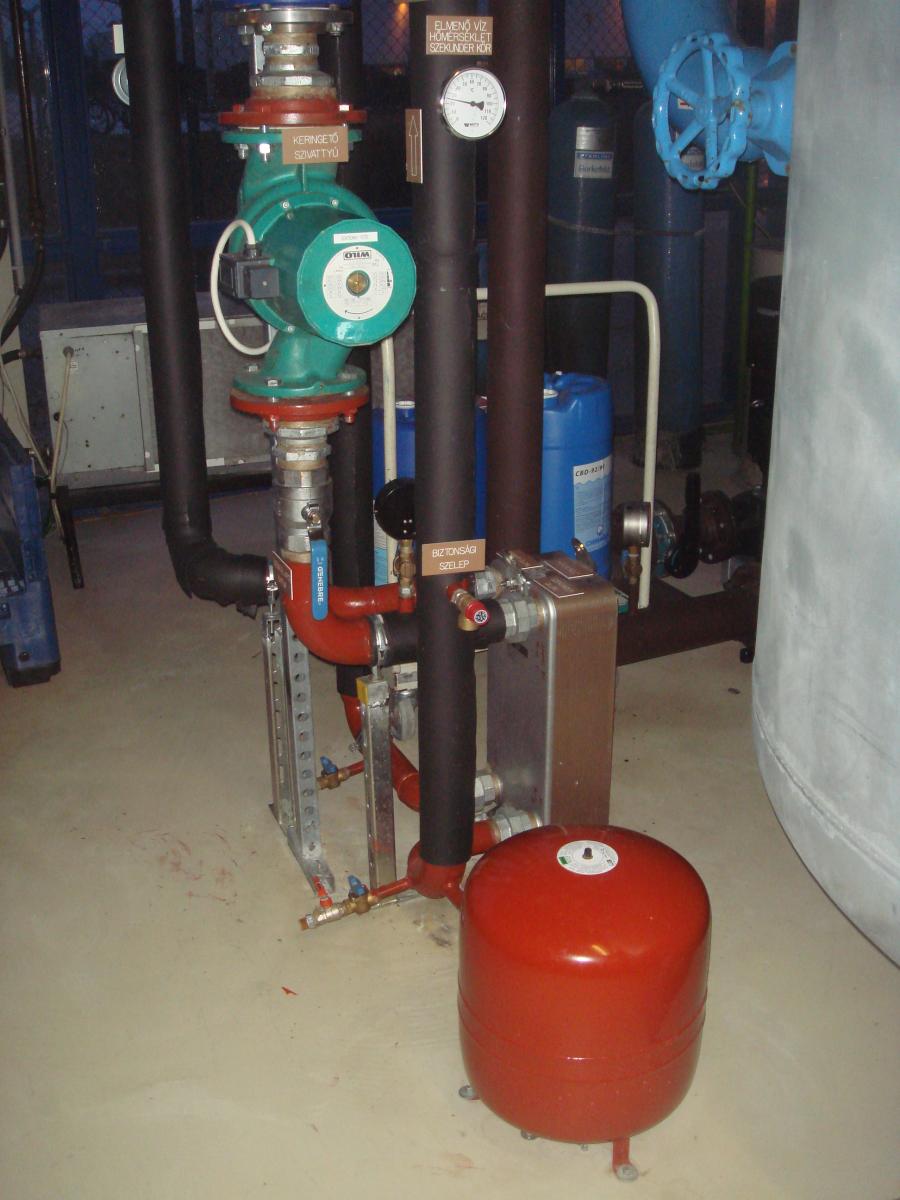
Figure 10 Free Cooling Plate and Frame
Calculating the savings is based upon the following formula.

Free Cooling projects can often be combined with heat recovery projects and allow using much of the same equipment and getting two types of savings, electric from shutting down an electric chiller, and gas from reducing the load on the makeup air heating units.
Figure 11 Free Cooling and Free Heating
Summary
Combining heat recovery projects together with HVAC projects described in the earlier article makes a combination where you can significantly reduce winter heat costs and have projects meeting our target of 1 year or less.
Source: coolingbestpractices