Tighter emissions requirements and underhood packing due to higher power demands from engines necessitate more optimized cooling packages. Fan and fan-shroud design is crucial for underhood airflow management. Fan shrouds funnel cooling air, which is sucked by the fan and passed through heat exchangers. Shroud design affects both the airflow and the noise generated by the fan.
The vehicle underhood compartment consists of the engine and cooling package. In heavy-duty trucks, the cooling package includes the heat exchanger, fan shroud and fan. To optimize the fan-shroud shape to maximize cooling air mass flow rates through the heat exchangers, researchers from Argonne National Laboratory, Cummins and CD-Adapco used the Adjoint approach to optimization. Adjoint optimization is an efficient sensitivity analysis method for aerodynamic shape and pressure drop evaluation.
The optimization process was accomplished using the Adjoint solver and mesh morpher in STAR-CCM+. First, a well-converged primal solution was obtained on a polyhedral mesh. The solution was solved steady-state, using a coupled solver approach and k-epsilon turbulence. A moving reference frame approach was used to simulate the effects of the moving geometry. The primal solution was driven to convergence by successively increasing the coupled solver Courant number.
Using the converged primal solution, a cost function of mass flow rate through the radiator with respect to fan-shroud position was solved on predefined control points near the fan-shroud surface to obtain a solution to the Adjoint equation. The solution to the Adjoint was used to calculate sensitivities of the primal flow to changes in control point position, resulting in a field of Adjoint sensitivity vectors on those points. The vectors were scaled to limit the maximum displacement of the morpher and produce a smoother transition to the optimal shape. The scaled sensitivity vector values were then used as displacements for the morpher. The morphing of the control points resulted in deformation of the mesh, and ultimately of the underlying fan-shroud geometry.
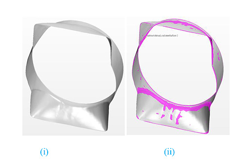
 Figure 1. The main difference between the original (i) and optimized (ii) fan shroud is variation in the shape of the surface edges.
The process of solving for the primal solution, Adjoint solution, Adjoint sensitivities, and mesh deformation was repeated 20 times to generate a cumulative displacement of the control points and the shroud geometry to increase the mass flow rate through the radiator. Figure 1 shows the original shroud surface, which consists of sharp edges when compared to the morphed/optimized surfaces. The highlighted areas show the modified/optimized edges that provide lower pressure loss and higher mass flow rates through the heat exchangers.
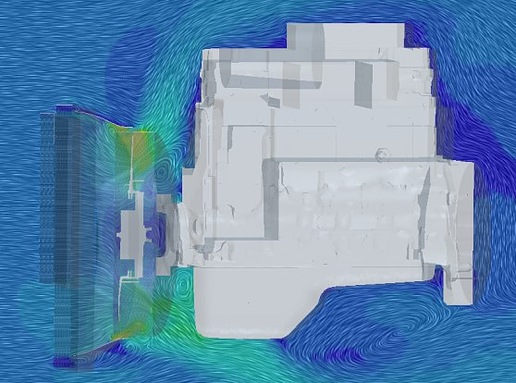
 Figure 2. Velocity contours. The velocity flows away smoothly from the fan.
Figure 2 reveals that the velocity flows away smoothly from the fan. In underhood compartments, stagnant flow zones are common between fan and engine block.
The optimization process resulted in a 1.4% increase in cold airflow with optimization of the fan-shroud surface. The improvement was primarily due to smoothing of the fan-shroud surface edges compared to the sharp edges in the original model. The airflow around the optimized edges was much smoother, as the edges act to reduce pressure losses and ultimately led to a higher mass flow rate through the heat exchanger. Further evaluation is ongoing to maximize the cooling air mass flow.
Source: sae.org